
FDK tutorial (part 1)
The FDK tutorial has two parts. In Part I, you will learn the basic command line options of the plastimatch drr and fdk commands. In Part II, you will learn how to use these commands to reconstruct data from a real CT scanner.
This is Part I of the FDK tutorial. You will download sample data, use the drr command to generate synthetic X-ray projections of the data, and then reconstruct them using the fdk command.
Download the sample data
https://sourceforge.net/projects/plastimatch/files/Sample%20Data/headphantom.mha.zip/download
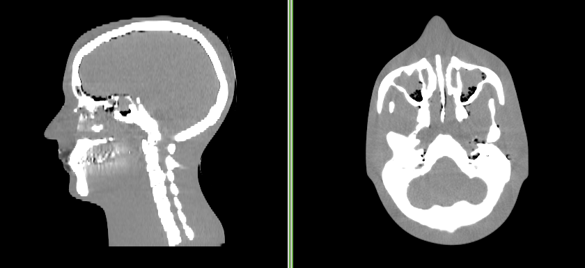
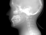
The sample data is a 3D volume of a CT scan of an acrylic head phantom. You can see what the original image looks below.
Make DRRs (first try)
Run the following command to create drr images:
plastimatch drr \
    -t pfm \
    -a 60 \
    -N 3 \
    -g "1000 1500" \
    -r "100 100" \
    -z "300 300" \
    -I headphantom.mha \
    -O head/
Note that the “/” at the end of the output directory “head” is important. If you forget this, the projection files will be created in the current directory. What you should get is a bunch of files in a directory like this:
head/0000.pfm
head/0000.txt
head/0001.pfm
head/0001.txt
...
Reconstruct the image (first try)
Run the following command to reconstruct the image:
plastimatch fdk -f none -r "100 100 100" -I head -O out.mha
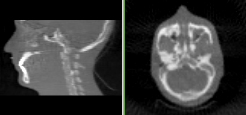
You should get an image like this:
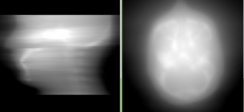
The image is kind of blurry, which is because we didn’t use the ramp filter. Try again with the ramp filter:
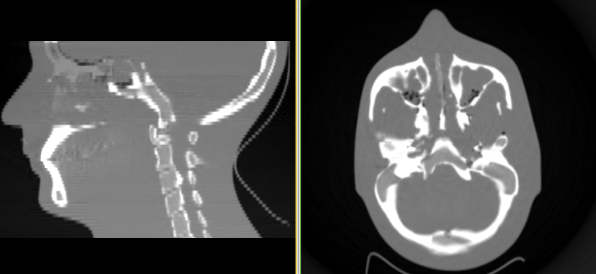
plastimatch fdk -f ramp -r "100 100 100" -I head -O out.mha
You should get an image like this:
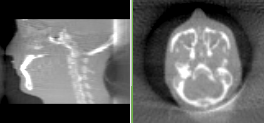
The artifact at the posterior of the skull is a truncation artifact, which is caused by missing data in the DRRs that we generated in the previous step. So let’s work on it, and get rid of it.
Looking at the DRRs
In order to get better control over the DRR generation process, we need to actually look at the DRRs. But unfortunately, there are not many good viewers for floating point images (especially for pfm format). Therefore we are going to make the drrs in pgm format first, and when we are satisfied with the results, we can make them in pfm.
Run the following command to create drr images in pgm format:
plastimatch drr \
    -t pgm \
    -a 60 \
    -N 3 \
    -g "1000 1500" \
    -r "100 100" \
    -z "300 300" \
    -I headphantom.mha \
    -O head/
If you didn’t delete the old images, you should see this:
head/0000.pfm
head/0000.pgm
head/0000.txt
head/0001.pfm
head/0001.pgm
head/0001.txt
...
When you look at the image in the image viewer such as gimp, you see this:

Not very interesting, is it. The problem is that the pgm is stored as 16-bit grayscale (values between 0 and 65535), but the DRR generates as floating point and doesn’t auto-scale the output. You need to manually scale it in order to see something interesting. Like this:
plastimatch drr \
    -t pgm \
    -a 60 \
    -N 3 \
    -s 150000 \
    -g "1000 1500" \
    -r "100 100" \
    -z "300 300" \
    -I headphantom.mha \
    -O head/
Which yields the following:
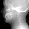
The truncation of the posterior of the head is clearly seen in the upper right corner of the image.
You might be wondering how I knew to scale by the value of 150000? For this, I used the “plastimatch stats” command to query the values in the pfm file:
$ plastimatch stats head/0000.pfm
Image center: 49.5 49.5
Projection matrix: 0 0.333333 0 0 0 0 -0.333333 0 -0.000666667 0 0 0.666667
MIN 0.000000 AVE 0.234049 MAX 0.588337 NUM 10000
Looking at the AVE and MAX values, I roughly estimated that multiplying the original values by 150000 would scale the intensities to the range (0 and 65535).
Make DRRs (second try)
There are several things I could do to fix the truncated projections, but the simplest is probably to make a bigger detector. The old detector was 30 x 30 cm. Let’s try a 30 x 40 detector, with a height of 30 cm and width of 40 cm. We’ll also increase the number of pixels a little to keep the pixels square.
plastimatch drr \
    -t pfm \
    -a 60 \
    -N 3 \
    -g "1000 1500" \
    -r "120 160" \
    -z "300 400" \
    -I headphantom.mha \
    -O head/
Which yields new DRRs with an increased field of view.
Reconstruct the image (second try)
Run the following command to reconstruct the image:
plastimatch fdk -f ramp -r "100 100 100" -I head -O out.mha
You should get an image like this:
While this image doesn’t have a truncation artifact, it quite low resolution. For our final effort, we will use more realistic image sizes.
Make DRRs (last try)
Let’s generate projection images that are equivalent to those acquired by a clinical radiotherapy scanner. Each image will be 768 x 1024 resolution (~0.380 mm at isocenter), and we’ll acquire 630 images per rotation.
plastimatch drr \
    -t pfm \
    -a 630 \
    -N 0.5714286 \
    -g "1000 1500" \
    -r "768 1024" \
    -z "300 400" \
    -I headphantom.mha \
    -O head/
It takes a long time. On my linux computer at home it took 17.0 minutes.
Reconstruct the image (last try)
When we reconstruct the images, we will change the resolution to 512 x 512 x 120, and reconstruct a volume of size 30 x 30 x 15 cm. This is equivalent to 1.25 mm slices, with an in-plane pixel size of 0.586 x 0.586 mm.
plastimatch fdk -f ramp -r "512 512 120" \
     -z "300 300 150" -I head -O out.mha
You should get an image like this:
This also takes a long time, but not quite as long as the DRR generation. On my linux computer at home it takes between 3 and 5 minutes. But the image quality is much improved over the low resolution version.