
fdk
The term FDK refers to the authors Feldkamp, Davis, and Kress who wrote the seminal paper “Practical cone-beam algorithm” in 1984. Their paper describes a filtered back-projection reconstruction algorithm for cone-beam geometries. The fdk program in plastimatch is an implmenetation of the FDK algorithm.
FDK usage
The fdk program takes a directory of 2D projection images as input, and generates a single 3D volume as output.
The command line usage is:
Usage: fdk [options]
Options:
 -A hardware            Either "cpu" or "cuda" (default=cpu)
 -a "num ((num) num)"   Use this range of images
 -r "r1 r2 r3"          Set output resolution (in voxels)
 -f filter              Either "none" or "ramp" (default=ramp)
 -s scale               Scale the intensity of the output file
 -z "s1 s2 s3"          Physical size of the reconstruction (in mm)
 -I indir               The input directory
 -O outfile             The output file
The usage of the fdk program is best understood by following along with the tutorials: FDK tutorial (part 1) and FDK tutorial (part 2).
Input files
Three different formats of input files are supported. These are:
Pfm format image files with geometry txt files
Raw format image files with geometry txt files
Varian hnd files
The pfm and raw files are similar, in that they store the image as an array of 4-byte little-endian floats. The only difference is that the pfm file has a header which stores the image size, and the raw file does not.
Each pfm or raw image file must have a geometry file in the same directory with the .txt extension. For example, if you want to use image_0000.pfm in a reconstruction, you should supply another file image_0000.txt which contains the geometry. A brief description of the geometry file format is given in Projection matrix file format.
The sequence of files should be stored with the pattern:
XXXXYYYY.ZZZ
where XXXX is a prefix, YYYY is a number, and .ZZZ is the extension of a known type (either .hnd, .pfm, or .raw).
For example the following would be a good directory layout for pfm files:
Files/image_00.pfm
Files/image_00.txt
Files/image_01.pfm
Files/image_01.txt
etc...
The Varian hnd files should be stored in the original layout. For example:
Files/ProjectionInfo.xml
Files/Scan0/Proj_0000.hnd
Files/Scan0/Proj_0001.hnd
etc...
No geometry txt files are needed to reconstruct from Varian hnd format.
Image geometry
By default, when you generate a DRR, the image is oriented as if the virtual x-ray source were a camera. That means that for a right lateral film, the columns of the image go from inf to sup, and the rows go from ant to post. The Varian OBI system produces HND files, which are oriented differently. For a right lateral film, the columns of the HND images go from ant to post, and the rows go from sup to inf. An illustration of this idea is shown in the figure below.
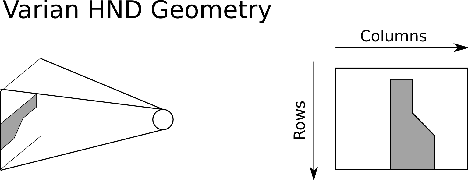
Geometry of Varian HND files